Correct Isolation Procedure
Essential steps for safe electrical isolation
Quick Navigation
Overview
Modern electrical work requires enhanced isolation verification that accounts for the possibility of diverted neutral current.
This procedure ensures that before any work begins on an electrical installation or system, all sources of energy have been identified, controlled, and verified as safe.
including potential diverted neutral currents that may energise bonded metal work or earthing systems even when the installation appears isolated.
The steps outlined below apply to both domestic and commercial installations, with particular attention to installations containing:
- Solar PV systems
- Battery Energy Storage Systems (BESS)
- EV charge points (including V2L/V2G capability)
- UPS units or standby generators
- Multiple distribution boards with shared neutrals (busbars)
- Steel gas mains
- Steel water mains
Step 1: Isolation Preparation
1.1 You must gain permission to isolate supplies for the work you are there to complete.
From a person of authority.
⚠️ Important: The duty holder, Authorised Person (AP), or responsible manager has legal authority over the equipment. You cannot isolate something that affects other people’s safety, production, or critical services without their authorisation.
(EAWR – 4(3), 12, 13. HASAWA – section 3. MHSWR. You must gain permission because EAWR 4(3), 12, and 13 legally require that isolation is controlled, authorised, and coordinated to prevent danger)
1.2 Confirm additional energy sources
Identify whether the installation includes:
- Solar PV systemsBattery Energy
- Storage Systems (BESS)EV charge points (including V2L/V2G capability)
- UPS units or standby generators
- Multiple distribution boards with shared neutrals
Identify ALL sources of supply.
(EAWR – 12, 13, 14, memorandum HSR25, HSG85, ESQCR – schedule 3)
⚠️ Important: EAWR Regs 12, 13, and 14, supported by HSR25, HSG85, BS 7671, and ESQCR. Legally require you to identify all sources of electrical energy, including secondary and tertiary supplies, before isolating a system.
Modern installations can energise circuits from multiple directions:
- Solar PV inverters BESS systems
- EV chargers with V2L/V2GUPS units
- Standby generators
- Shared neutrals between DBs Parallel supplies
- Smart meters with internal relays
If you isolate only the main switch at the start of a system but another source can still energise the circuit, the system is not dead.
1.3 Complete your Risk assessment and method statement.
(You are there, nobody can assess the risks better)
(MHSWR – 3, 5, 10, 12. HSWA – section 2, 3,7. EAWR – 4(3), 12, 13, 14. CDM – 15, 8.)
⚠️ Important: You complete your RAMS on site because the law requires a “suitable and sufficient” assessment of the actual risks, and only the competent person on site can do that.
Step 2: Shut Down and Isolate PV Systems
PV arrays generate energy whenever illuminated. They must be fully isolated before any other work can take place. You must search, enquire, locate, isolate and lock off the PV system.
2.1 Follow inverter shutdown procedures (generic)
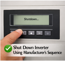
- Shut down the inverter using the manufacturer's sequence
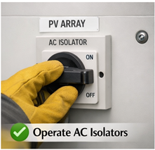
- Operate AC isolators
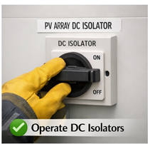
- Operate DC isolators
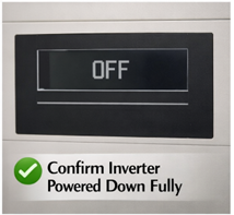
- Confirm the inverter has powered down fully
- Lock off and isolate the AC and DC isolators
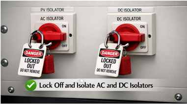
(A picture of the isolation is great proof you did it)
UK BASED MANUFACTURERS
1. GivEnergy (UK)
- Website: https://www.givenergy.co.uk
- Technical: https://www.givenergy.co.uk/resources
2. Sunsynk (UK HQ, global manufacturing)
- Website: https://www.sunsynk.com
- Technical: https://www.sunsynk.com/downloads
3. BPC Energy
- Website: https://www.bpc-ups.com
- Technical: https://www.bpc-ups.com/downloads
4. Voltacon Solar
- Website: https://www.voltaconsolar.com
- Technical: https://www.voltaconsolar.com/downloads
5. Ensmart Power
- Website: https://www.ensmartpower.com
- Technical: https://www.ensmartpower.com/downloads
6. Rayleigh Instruments
- Website: https://www.rayleigh.com
- Technical: https://www.rayleigh.com/downloads
7. Eco Worthy UK
- Website: https://eco-worthy.co.uk
- Technical: https://eco-worthy.co.uk/pages/download
GLOBAL MANUFACTURERS SOLD IN THE UK
8. Huawei
- Website: https://solar.huawei.com/eu
- Technical: https://solar.huawei.com/eu/download
9. Solis (Ginlong)
- Website: https://solar.huawei.com/eu
- Technical: https://solar.huawei.com/eu/download
10. Growatt
- Website: https://www.growatt.com
- Technical: https://www.growatt.com/download
11. Sofar Solar
- Website: https://www.sofarsolar.com
- Technical: https://www.sofarsolar.com/download
12. Fox ESS
- Website: https://www.sofarsolar.com
- Technical: https://www.sofarsolar.com/download
13. Deye
- Website: https://www.deyeinverter.com
- Technical: https://www.deyeinverter.com/download
14. Hoymiles
- Website: https://www.hoymiles.com
- Technical: https://www.hoymiles.com/resources
15. Afore
- Website: https://www.aforenergy.com
- Technical: https://www.aforenergy.com/download
16. SAJ
- Website: https://www.saj-electric.com
- Technical: https://www.saj-electric.com/download
GERMANY
17. SMA Solar
- Website: https://www.sma.de
- Technical: https://www.sma.de/en/products/downloads (sma.de in Bing)
18. Fronius
- Website: https://www.fronius.com
- Technical: https://www.fronius.com/en/solar-energy/installers-partners/technical-data (fronius.com in Bing)
19. Kostal
20. Kaco
- Website: https://www.kaco-newenergy.com
- Technical: https://www.kaco-newenergy.com/en/downloads
ISRAEL
21. SolarEdge
- Website: https://www.solaredge.com/uk
- Technical: https://www.solaredge.com/uk/support/downloads (solaredge.com in Bing)
USA
22. Enphase
- Website: https://www.enphase.com/en-uk
- Technical: https://www.enphase.com/en-uk/support
23. Tesla (Powerwall + Gateway inverter)
- Website: https://www.tesla.com/powerwall
- Technical: https://www.tesla.com/support/energy/powerwall/owner-resources (tesla.com in Bing)
AUSTRIA
24. Fronius
(Already listed under Germany/Austria)
JAPAN
25. Panasonic (legacy microinverters)
- Website: https://www.panasonic.com
- Technical: varies by region
26. Omron
- Website: https://www.omron.com
- Technical: https://www.omron.com/global/en/download (omron.com in Bing)
ITALY
27. Fimer (formerly ABB Solar)
- Website: https://www.fimer.com
- Technical: https://www.fimer.com/download
SOUTH KOREA
28. LG Electronics (legacy PV inverters)
- Website: https://www.lg.com
- Technical: legacy support only
SPAIN
29. Ingeteam
- Website: https://www.ingeteam.com
- Technical: https://www.ingeteam.com/solar/downloads
CZECH REPUBLIC
30. Solax Power (HQ China, EU operations)
- Website: https://www.solaxpower.com
- Technical: https://www.solaxpower.com/downloads
2.2 Consider hybrid inverters
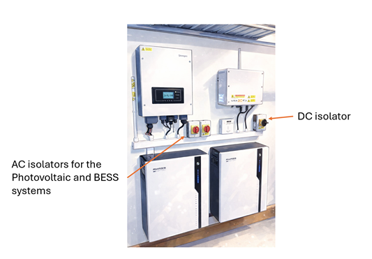
Hybrid systems may continue energising circuits from the battery even when the grid is down. Ensure both AC and DC sides are isolated.
UK BASED HYBRID MANUFACTURERS
1. GivEnergy (UK)
- Website: https://www.givenergy.co.uk
- Technical: https://www.givenergy.co.uk/resources
2. Sunsynk (UK HQ, global manufacturing)
- Website: https://www.sunsynk.com
- Technical: https://www.sunsynk.com/downloads
3. Voltacon Solar
- Website: https://www.voltaconsolar.com
- Technical: https://www.voltaconsolar.com/downloads
4. Ensmart Power
- Website: https://www.ensmartpower.com
- Technical: https://www.ensmartpower.com/downloads
GLOBAL MANUFACTURERS SOLD IN THE UK
CHINA (HYBRID MODELS SOLD IN UK)
5. Fox ESS
- Website: https://www.fox-ess.com
- Technical: https://www.fox-ess.com/downloads
6. Solis (Ginlong) – Hybrid Series
- Website: https://www.solisinverters.com
- Technical: https://www.solisinverters.com/download
7. Growatt – SPH / MOD Hybrid
- Website: https://www.growatt.com
- Technical: https://www.growatt.com/download
8. Sofar Solar – HYD Series
- Website: https://www.sofarsolar.com
- Technical: https://www.sofarsolar.com/download
9. Deye – SUN Hybrid Series
- Website: https://www.deyeinverter.com
- Technical: https://www.deyeinverter.com/download
10. SAJ – H1 Hybrid Series
- Website: https://www.saj-electric.com
- Technical: https://www.saj-electric.com/download
11. Afore – Hybrid Series
- Website: https://www.aforenergy.com
- Technical: https://www.aforenergy.com/download
ISRAEL
12. SolarEdge – Energy Hub Hybrid
- Website: https://www.solaredge.com/uk
- Technical: https://www.solaredge.com/uk/support/downloads (solaredge.com in Bing)
USA
13. Enphase – IQ Battery + Microinverter Hybrid System
(Not a single hybrid unit, but a hybrid system — still sold as hybrid in UK)
- Website: https://www.enphase.com/en-uk
- Technical: https://www.enphase.com/en-uk/support
14. Tesla – Powerwall + Gateway (AC coupled hybrid)
- Website: https://www.tesla.com/powerwall
- Technical: https://www.tesla.com/support/energy/powerwall/owner-resources (tesla.com in Bing)
EUROPE
15. Fronius – GEN24 Hybrid
- Website: https://www.fronius.com
- Technical: https://www.fronius.com/en/solar-energy/installers-partners/technical-data (fronius.com in Bing)
16. Kostal – Plenticore Hybrid
17. Ingeteam – Hybrid Series
- Website: https://www.ingeteam.com
- Technical: https://www.ingeteam.com/solar/downloads
ITALY
18. Fimer (ABB) – Hybrid Series
- Website: https://www.fimer.com
- Technical: https://www.fimer.com/download
Step 3: Isolate BESS
BESS units can supply significant fault current and may automatically reconnect.
Locate all UPS and BESS systems. Enquire, search, locate and isolate or unplug all UPS and BESS systems. These can also be found under desks for stand alone IT equipment or they can power whole floors of IT equipment.
Please be aware Medical locations have special rules for working on BESS (HTM 06-01, HTM 06-02, HTM 06-03, HTM05-02, HTM 03-01, DSEAR 2002)
3.1 Perform full BESS isolation (generic)
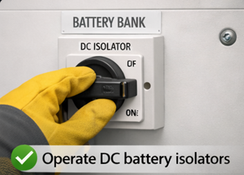
- Operate DC battery isolators
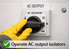
- Operate AC output isolators
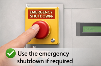
- Use the emergency shutdown if required
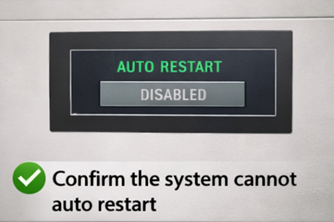
- Use the emergency shutdown if required
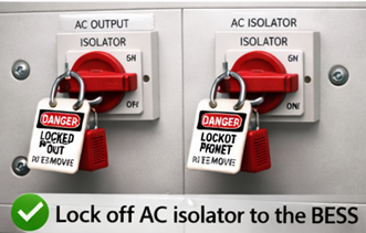
- Lock off AC isolator to the BESS
UK BASED & UK OPERATING MANUFACTURERS
1. GivEnergy (UK)
- Website: https://www.givenergy.co.uk
- Technical: https://www.givenergy.co.uk/resources
2. Sunsynk (UK HQ, global manufacturing)
- Website: https://www.sunsynk.com
- Technical: https://www.sunsynk.com/downloads
3. Voltacon Solar
- Website: https://www.voltaconsolar.com
- Technical: https://www.voltaconsolar.com/downloads
4. Ensmart Power
- Website: https://www.ensmartpower.com
- Technical: https://www.ensmartpower.com/downloads
5. Riello UPS (UK division)
- Website: https://www.riello-ups.co.uk
- Technical: https://www.riello-ups.co.uk/downloads
6. Socomec UK
- Website: https://www.socomec.co.uk
- Technical: https://www.socomec.co.uk/resources
7. Borri UK
- Website: https://www.borri.co.uk
- Technical: https://www.borri.co.uk/downloads
8. Energy Solutions (EasyGrid BESS)
- Website: https://www.energy-solutions.co.uk (energy-solutions.co.uk in Bing)
- Technical: https://www.energy-solutions.co.uk/technical-library (energy-solutions.co.uk in Bing)
9. Connected Energy (E STOR BESS)
- Website: https://www.connected-energy.co.uk (connected-energy.co.uk in Bing)
- Technical: https://www.connected-energy.co.uk/resources (connected-energy.co.uk in Bing)
10. AceOn Group (UK)
- Website: https://www.aceongroup.com
- Technical: https://www.aceongroup.com/resources
11. Multi Source Power (UK)
- Website: https://www.multisourcepower.com
- Technical: https://www.multisourcepower.com/resources
GLOBAL MANUFACTURERS SOLD IN THE UK (IMPORTED)
12. Fox ESS (China)
- Website: https://www.fox-ess.com
- Technical: https://www.fox-ess.com/downloads
13. Solis / Ginlong (China)
- Website: https://www.solisinverters.com
- Technical: https://www.solisinverters.com/download
14. Huawei (China) – UPS & LUNA BESS
- Website: https://e.huawei.com
- Technical: https://support.huawei.com/enterprise/en
15. BYD (China) – Battery Box BESS
- Website: https://www.bydbatterybox.com
- Technical: https://www.bydbatterybox.com/downloads
16. Pylontech (China)
- Website: https://www.pylontech.com.cn
- Technical: https://www.pylontech.com.cn/service/support
17. Alpha ESS (China)
- Website: https://www.alpha-ess.com
- Technical: https://www.alpha-ess.com/support/download
18. Solax Power (China)
- Website: https://www.solaxpower.com
- Technical: https://www.solaxpower.com/downloads
19. Tesla Energy (USA)
- Website: https://www.tesla.com/energy
- Technical: https://www.tesla.com/support/energy
20. LG Energy Solution (Korea)
- Website: https://www.lgensol.com
- Technical: https://www.lgensol.com/global/support/product-info (lgensol.com in Bing)
21. Enphase (USA) – IQ Battery
- Website: https://www.enphase.com/uk
- Technical: https://www.enphase.com/uk/support
22. APC (Schneider Electric – France/Global)
- Website: https://www.apc.com
- Technical: https://www.apc.com/uk/en/tools/download (apc.com in Bing)
23. Eaton (USA/Global)
- Website: https://www.eaton.com
- Technical: https://www.eaton.com/gb/en-gb/support/product-support.html (eaton.com in Bing)
24. Vertiv / Liebert (USA/Global)
- Website: https://www.vertiv.com
- Technical: https://www.vertiv.com/en-emea/support
25. AEG Power Solutions (Germany)
- Website: https://www.aegps.com
- Technical: https://www.aegps.com/en/support/downloads (aegps.com in Bing)
26. Tripp Lite (USA, now Eaton)
- Website: https://www.eaton.com
- Technical: https://www.eaton.com/gb/en-gb/support/product-support.html (eaton.com in Bing)
27. Sonnen (Germany)
- Website: https://sonnenbatterie.co.uk (sonnenbatterie.co.uk in Bing)
- Technical: https://sonnenbatterie.co.uk/downloads (sonnenbatterie.co.uk in Bing)
3.2 Verify isolation
Some BESS units have internal capacitors or delayed shutdown sequences. Wait for confirmation indicators to extinguish.
“Some Battery Energy Storage Systems contain large internal capacitors or have built‑in delayed shutdown sequences, meaning they continue to hold dangerous electrical energy even after the external isolator has been switched off. Because of this, the system may remain energised internally for several seconds or even minutes; while it safely discharges stored energy. To avoid accidental contact with live components, you must wait until all confirmation indicators, status LEDs, or “DC bus charged” lights have fully extinguished before proceeding. These indicators are the manufacturer’s way of showing that the internal circuits have discharged and the system is genuinely safe to work on.”
Step 4: Disable or Isolate EV Charge Points
- V2L/V2G systems can energise circuits independently
- Internal relays may close unexpectedly
- Line
- Neutral
- Earth monitoring circuits
- DC charging circuits (for rapid chargers)
- PEN‑fault detection circuits
- Pilot/CP signalling hardware
These relays are electronically controlled, not manually operated. Because of that, they can change state on their own when certain conditions occur.
The charger can close a relay even when you think it’s “off”
EV chargers often stay powered internally even when the output is “off”. So a relay can close when:
- the charger runs a self‑test
- the PEN‑fault detection circuit injects a test voltage
- the CP/PP signalling changes
- the firmware reboots
- the charger detects a vehicle connection
- the charger thinks it needs to re‑establish earth monitoring
This can happen without warning.
You can hear a “click” and see voltage appear on the output
Because the relay physically closes, you may suddenly get:
- 230 V appearing on the output terminals
- a neutral‑earth voltage appearing
- a small DC test voltage
- a continuity path you didn’t expect
This is why EV chargers are not safe to test like normal circuits.
Even during isolation, internal capacitors and relays can re‑energise parts of the circuit
Some chargers:
- keep the logic board powered
- keep the PEN‑fault circuit powered
- keep the CP/PP signalling alive
- run periodic internal checks
During these checks, a relay may momentarily close. This is why you can get:
- “ghost” voltages
- NCV pens lighting up
- clamp meters showing small currents
- unexpected continuity readings
EV chargers can energise themselves internally, even when you think they’re off. Their relays can close automatically during self‑tests, firmware checks, or PEN‑fault monitoring.
This is why:
- you NEVER trust the output terminals
- you ALWAYS isolate upstream
- you NEVER rely on the charger’s own “off” state
- you ALWAYS verify dead at the supply, not the charger
- PEN fault detection devices can introduce voltages during testing
A PEN‑fault detection device (the ones used on EV chargers, BESS, PME systems, etc.) sometimes injects a small test voltage onto the earth/neutral path on purpose.
It does this to check:
- whether the PEN conductor is intact
- whether the earth is floating
- whether the system is safe to energise
This is normal behaviour for these devices.
Why they introduce voltage?
Because the device has no other way to know if the PEN is broken. So it momentarily applies a small internal voltage (often 12–18 V, sometimes up to 30–40 V depending on design) between:
- Line → Earth
- Neutral → Earth
Then it measures what happens.
If the voltage behaves in a certain way, the device knows:
- PEN intact → safe
- PEN broken → dangerous → disconnect
Why this matters for you
Because your test instruments will see that voltage. So during testing you might measure:
- unexpected voltage on the earth
- “phantom” voltage on the neutral
- small AC or DC potentials that weren’t there before
- NCV pens lighting up
- single‑pole testers triggering
- clamp meters showing small currents
This is not a real supply fault, it’s the PEN‑fault device doing its self‑test.
The danger
If you don’t know this is happening, you might think:
- the earth is live
- there’s a diverted neutral
- there’s a PME failure
- the system is unsafe
When actually it’s just the device injecting its test voltage.
The device itself can create a voltage on the earth/neutral during testing. This is expected behaviour, not a fault.
But it means:
- your readings can be misleading
- NCV pens will trigger
- single‑pole testers will light
- clamp meters may show small currents
- you must isolate properly before testing
- V2L/V2G systems can energise circuits independently
V2L/V2G units contain internal inverters and contactors that can export power on their own, without the house supply being present. So even if the main installation is isolated, the vehicle can back‑feed and energise a circuit the moment its internal relays close or its firmware decides export is allowed.
In other words: The car itself becomes a live source, completely independent of the grid. EV’s generally have a potential of 900V DC
4.1 Isolation steps
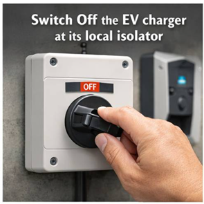
- Switch off the EV charger at its local isolator
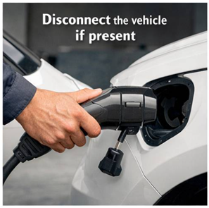
- Disconnect the vehicle if present
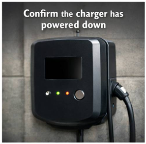
- Confirm the charger has powered down
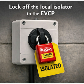
- Lock off the local isolator to the EVCP
Step 5: Shed Loads on Other Distribution Boards
In multi DB installations, parallel neutral paths can remain energised even after the main switch is off.
Electrical Reasoning
- Shared neutrals create return paths between boards. Even if one main switch is off, current can flow through the neutral link from another energized board.
- This means the supposedly “dead” board can still have energised metalwork or voltage on the neutral bar, posing a shock risk.
- In UK PME or TN‑C‑S systems, these parallel paths can carry diverted neutral current (DNC) from the supply side, keeping the neutral at a potential above true earth.
- In a busbar system, multiple DBs share a common neutral bar, creating inherent parallel neutral paths, so isolating only one board does not break neutral continuity and therefore all boards on that shared busbar must be isolated to eliminate backfeed risk.
Safety Implications
- If only one DB is isolated, the neutral remains bonded to other live boards, so testing “dead” could give false readings.
- Isolating all DBs ensures every neutral path is opened, removing any backfeed or cross‑connection.
- It also prevents touch voltage rise on exposed metalwork and guarantees that earth leakage clamps show zero current before work begins.
Even without a formal busbar chamber, parallel neutrals can still exist if neutrals are cross‑connected (for example, shared containment, common neutral link, or UPS/standby supply interconnections).
So the same hazard applies, energised neutrals can remain live through other boards.
If the DBs share a common neutral return, whether through a busbar chamber or interlinked neutrals, you must treat it as a busbar‑type system for isolation purposes — isolate every board that shares that neutral path.
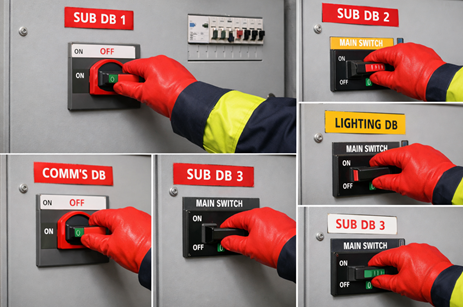
5.1 Isolate all secondary DBs
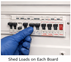
- Shed the loads on each of these boards
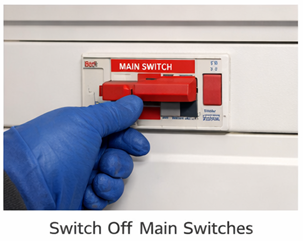
- Switch off main switches on all sub boards
- Disable UPS units, standby supplies, and load shedding systems

(Confirm no automatic transfer systems can re energise circuits)
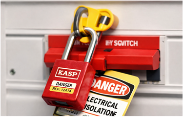
- Apply isolation lock off to all main switches
5.2 Be aware of bonding
Bonded metalwork can still carry diverted neutral current even after all Distribution Boards are isolated.
Even after all distribution boards are isolated, bonded metalwork can still carry diverted neutral current because the current doesn’t only flow through live conductors, it can also return via parallel earth or bonding paths connected to the supply network.
Brief Explanation
- Shared neutrals create return paths between boards. Even if one main switch is off, current can flow through the neutral link from another energized board.
- This means the supposedly “dead” board can still have energised metalwork or voltage on the neutral bar, posing a shock risk.
- In UK PME or TN‑C‑S systems, these parallel paths can carry diverted neutral current (DNC) from the supply side, keeping the neutral at a potential above true earth.
- In a busbar system, multiple DBs share a common neutral bar, creating inherent parallel neutral paths, so isolating only one board does not break neutral continuity and therefore all boards on that shared busbar must be isolated to eliminate backfeed risk.
- In PME (TN‑C‑S) systems, the neutral and earth are combined at the supply side.
- If there’s neutral imbalance or a fault on the supply PEN conductor, current can divert through metallic services (water, gas, structural steel) that are bonded to earth.
- These paths remain connected to the wider network even when all DBs are switched off, so the metalwork can still sit at a potential above true earth and carry residual current.
5.3 Generators and Why They Need Isolating
Generators are alternative sources of electrical power that can supply energy to an installation when the main utility supply fails or is intentionally disconnected.
They convert mechanical energy (from an engine or turbine) into electrical energy through electromagnetic induction, feeding circuits via their output terminals.
Why Generators Must Be Isolated
- Prevent Backfeed: When the generator is connected to the same system as the mains supply, it can energise cables and equipment that are assumed to be dead, creating a severe shock or fire hazard.
- Protect Personnel: Isolation ensures that maintenance or testing can be carried out safely without risk of the generator energising circuits unexpectedly.
- Protect Equipment: Prevents damage to the generator and switchgear caused by parallel operation with the mains supply unless specifically designed for synchronised operation. (syncing the frequency of both waveforms)
- Comply with Regulations: BS 7671 Section 551 requires that generators have means of isolation and interlocking to prevent inadvertent connection to other sources.
Generators must be fully isolated from all other supplies before work begins to ensure no backfeed, no parallel energisation, and complete electrical safety for personnel and equipment.
- Stop the generator safely Shut the generator down using its normal stop control so it comes off load before isolation.

- Operate the generator’s main isolator Turn the generator output isolator to the OFF position. This breaks the generator’s connection to the installation.
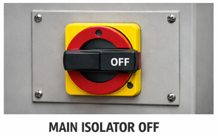
- Lock off the isolator Apply a padlock and tag to the generator isolator so it cannot be re energised accidentally.

- Isolate the changeover arrangement If the installation uses a manual or automatic changeover switch, isolate and lock off the relevant side so the generator cannot backfeed the mains or vice versa.

Disconnecting the batteries which feed the alternator and starting circuits will generally stop the generator from physically starting.
Step 6: Approach the Intake Position
Once the PV, BESS, EV, UPS, Generators, and all distribution boards have been fully isolated, move to the intake position; this is where the main incoming supply and earthing system are located for the installation.
This level of isolation and verification applies to installation electricians working on whole installation risks, it does not apply to plumbers or trades who typically only deal with a single spur, fused connection unit, or local circuit.
Their work is normally limited to one clearly defined supply, whereas electrical isolation often involves multiple energy sources that must all be identified and made safe.
This step ensures you’re working at the point where all external energy sources converge, allowing safe verification that the entire system is de‑energised before proceeding.
By checking there, you can prove the entire system is truly dead, because that’s the only location where all external and internal energy paths meet.
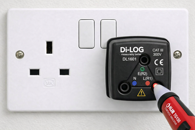
6.1 Prove your contact voltage indicator is functioning correctly on a known live source
Using a BS 1363 Socket Test Adapter and putting your contact voltage tester probe into the live terminal should produce contact and a visual indication of functionality.
6.2 Test the surface of the incoming equipment for “Tracking”
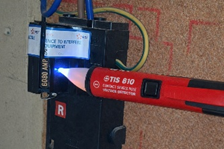
- Place the contact voltage indicator on to the surface of the incoming equipment
- If this indicates voltage present then this is a dangerous situation.
- Retest your contact voltage indicator.
- If tracking is present then you must phone 105 immediately and report dangerous equipment.
“Hi, I’m an engineer on site. I’ve carried out safety checks on the incoming supply and I’m reporting a dangerous condition. I’ve identified tracking on the main service head using a contact voltage indicator. There are clear signs of unintended energisation on the head, and I cannot guarantee the stability of the touch voltage or the safety of the installation.
I’ve stopped work, isolated what I safely can, and I need this escalated as an urgent attendance from the DNO. Can you log this as a potentially dangerous service head fault and dispatch an engineer as soon as possible?”
A contact voltage indicator if single band is measuring 90-1000V if it is dual band then it is measuring 12-48V and 90-1000V.
6.3 Measure the main earth to check for the presence of current
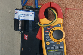
- Place your current-transformer ammeter (clamp meter) on the main incoming earth
- Have you detected any current?
- Note down the reading you have acquired
Depending on how much current is detected it could be DNC, Earth leakage or an internal fault on the property generating the reading. 15mA is considered a dangerous consistent level of current on an electrode designed according to BS7671 to dissipate fault currents.
- Gain permission to isolate the entire property beyond the incoming supply.
- Adjust your RAMS you are now fault finding
a full isolation to determine source of the current then you should test the metal-work for a driving voltage.
If the client refuses proceed to step 7.2
6.4 With permission to fault find
- Operate the main switch
- Did the reading on the current-transformer ammeter change?
- A slight reduction in current will be the properties earth leakage disappearing upon the main switch opening.
- If the current disappears drastically then this property likely has an INTERNAL FAULT driven by internal loading
- If the current does not change then there is an external fault. Being driven by external loads
- High Net currents – The 15 mA danger threshold comes from IEC/BS EN 60479‑1 (effects of electric current on the human body).
- Lock off the main switch
- Apply warning notices
- unusual readings require investigation
Is it in the house or in the street?
If current vanishes then you know this is an internal fault to the electrical system within this property, insulation somewhere is breaking down and there is a leakage to earth due to that.
You cannot do anything if it is not a fault or leakage current from within the property.
Step 7: With the installation isolated, test for VOLTAGE
Test the main earth with your non contact voltage indicator.
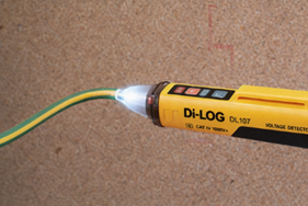
(Is there a gap between 49V and 90V? I need to research this I think there is)
Duel band indicator will be 12V minimum
7.1 Test Exposed Conductive Parts
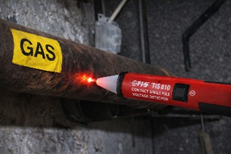
Check:
- Taps
- Radiators
- Appliance casings
- Structural steel or other extraneous conductive parts
If your contact voltage indicator does highlight a voltage present then there is a dangerous risk of the current that is present being driven into a human being, if their resistance barrier is breached.
These are issues you cannot fix as a tradesperson, it is a network issue.
7.2 Client/DNO refusal to investigate causes….
12v contact voltage and 15mA……
“Falls in to Zone 3 (“can’t‑let‑go” region): strong muscular contraction, difficulty releasing contact, possible respiratory interference but USUALLY no ventricular fibrillation. (based on adult physiology) About 800 Ω total impedance would allow 15 mA to flow at 12 V. That’s consistent with damp, wet or damaged skin contact.”
(IEC 60479‑1 Table A.1 and Figure 20 define these current zones)
With the voltage level and current level you can determine the resistance required or lack of which would create a dangerous situation.
“In a PME system, any measurable current on bonded metalwork must be driven by a neutral – earth potential difference, because current cannot flow without a voltage source; a principle explicitly stated in ENA Engineering Report P24: PME Conditions and the Risk of Electric Shock. Which explains that PME creates parallel neutral return paths through pipework, structural steel and bonding, and that these paths will carry current whenever a neutral – earth voltage exists.
ENA ER G12/4 reinforces this by stating that bonded metalwork forms part of the neutral return path and that the presence of current indicates a neutral – earth potential difference and therefore a diverted neutral current condition.
BS 7671:2018+A2:2022, Section 411 and Annex A, further confirms that PME systems inherently allow neutral current to flow in protective and bonded conductors whenever a voltage difference exists.
IEC 60364 4 41 and IEC/TS 60479 1 provide the physiological and touch voltage basis, establishing that 15 mA is within the “painful/involuntary reaction” (to ADULTS) zone and therefore represents a hazardous touch current if accessible.
Because 12 V and 15 mA on bonded pipework proves the existence of a real neutral–earth voltage and a low impedance diverted neutral path, this condition must be reported under DNO safety policy: it is consistent with diverted neutral current, and both G12/4 and P24 identify such conditions as requiring investigation due to the risk of PEN conductor deterioration and dangerous rise of touch voltage.”
If your professional judgment determines dangerous you must issue a danger notice to the client, log the current and voltage levels with the dno via 105
“Hi, I’m an engineer on site. I’m reporting a potentially dangerous supply related condition. I’ve measured current on the main earth conductor, the reading is at a level that could indicate a diverted neutral current, earth leakage, or an internal fault.
I requested permission to isolate the entire installation beyond the incoming supply so I could carry out further fault finding, but the client refused access. Because I cannot safely isolate, I cannot determine whether the issue is internal or coming from the network.
I have tested the accessible metalwork for driving voltage, and based on the voltage and current levels present, my professional judgement is that the situation may be dangerous.
I have issued a danger notice to the client, stopped work, and I’m now logging the current and voltage levels with you. Can you please record this as a potentially dangerous supply condition and arrange for a DNO engineer to attend?”
Phone your CPS provider as soon as you can and log with them on YOUR file, the time date, address, DNO call log numbers; any information that you can that will SHOW that you have been diligent in your work.
7.3 External fault detected
Proceed to step 9.
8.0 Prove Dead - If no DNC detected
With the presence of DNC current alleviated and managed you can proceed to complete your original task. This could be a single circuit or an entire installation depending on your “scope”
Determine the correct circuit/system and test between:
Single phase
- Live–Neutral
- Live–Earth
- Neutral–Earth
Three Phase
- Neutral - Line 1
- Neutral - Line 2
- Neutral - Line 3
- Earth - Line 1
- Earth - Line 2
- Earth - Line 3
- Line 1 - Line 2
- Line 1 - Line 3
- Line 2 - Line 3
- Neutral - Earth
8.1 Complete your initial task
You have isolated all secondary and tertiary supplies, checked for DNC currents and voltage to drive it and you deem it totally acceptable to proceed with your work after safely isolating the supply with the correct isolation procedure.
9: Reporting and Next Steps
If DNC, NET, or a suspected PEN fault is identified:
9.1 Report immediately
If you suspect human resistance thresholds could be breached.
- Call 105 (UK DNO emergency number) and report:
- Measured current
- Generalised voltage measurement or direct measurement
- Voltage fluctuations if they are occurring
- Current on bonding conductors measured by your clamp meter
- Signs of open circuit neutral - voltage and current on bonding and earthing
- Any shock incidents or unusual heating reported by client or you can see after investigation
9.2 The Client
- A supply-side issue has been identified and reported to the Distribution Network Operator (DNO)
- Until the DNO attends and resolves the fault, no one should touch exposed metalwork, bonded pipework, or any conductive parts that could become energised
9.3 Provide supporting evidence
Share:
- Voltage readings
- Bonding conductor current measurements
- Photographs of damage or overheating
9.4 Do not re-energise the installation until deemed safe by the DNO to do so
9.5 First steps upon returning
When you return to the installation after the DNO has attended, your first priority is to verify that the installation remains safely isolated and that none of your previous safety measures have been disturbed. Proceed methodically:
1. Confirm All Isolations Are Still in Place
Before touching anything, visually and physically check every lock‑off, tag, and isolation point you previously applied. Nothing should be assumed — confirm each isolation individually.
2. Check for Residual or Returning Voltage
Use a non-contact voltage tester on:
- The service head (this should be new if tracking was found)
- The incoming neutral this (should show voltage)
- The earthing conductor leaving the service head (this should not show voltage)
If the device indicates the presence of voltage, treat the installation as potentially energised and reassess before proceeding.
3. Measure Current on the Main Earthing Conductor
Use a clamp meter to check whether any current is still flowing on the main earth conductor.
- Zero or near‑zero current suggests the DNO has resolved the supply‑side issue
- Any measurable current requires further investigation before work continues
4. Verify Integrity of Bonding Connections
Confirm that all bonding conductors remain securely connected to:
- The MET
- Gas pipework
- Water pipework
- Structural steel or other extraneous conductive parts
Any loose or disturbed bonding must be corrected before proceeding.
5. Assess Whether Conditions Have Changed
Compare your new readings with the measurements taken before the DNO attended. If:
- Neutral‑to‑earth voltages have normalised
- Bonding conductor currents have dropped
- No unexpected voltages are detected on metalwork
…then it is reasonable to assume the supply-side fault has been rectified.
Only once all checks confirm a safe condition should you consider removing isolations or resuming the original task.